
Introduction
Upon arrival at the site, the original lifting capacity of a telescopic crane is merely a starting point. The difference between a smooth lift and a catastrophic overturning is almost always rooted in the details of setup: the way the outriggers are positioned, the chosen boom angle, and whether the ground conditions have been properly verified. According to Subpart CC data from the U.S. Occupational Safety and Health Administration (OSHA), since 2019, improper use of outriggers or stabilizers has ranked as one of the top three crane-related violations in the construction industry (osha.gov). Therefore, a rigorous and repeatable setup protocol not only protects personnel and assets but also ensures project timelines and profitability.
This article distills manufacturer manuals, the latest OSHA guidelines, and field-proven best practices into an actionable roadmap for safe and efficient deployment. The language is concise and clear, avoiding technical jargon, so that planners, operators, and inspectors can agree on common maintenance standards.
1. Why is precise setting important
A telescopic crane is like a giant lever. When the boom extends or swings, the load moment (weight × radius) causes the center of gravity of the machine to move towards the overturning axis. The outriggers expand the base polygon and counteract this shift; the boom angle determines the rate at which the moment increases. If any component fails, the safety margin will be exhausted before reaching the rated lifting capacity. Industry accident reports show that over 60% of mobile crane rollover accidents are related to partial or uneven deployment of the outriggers, usually on seemingly “solid” but untested ground.
Key points
No crane can maintain stability solely through its tires.
Unless otherwise explicitly stated, the load diagram assumes that the legs are fully extended on flat ground.
Even a slight change in angle near the horizontal can significantly increase the overturning force.
2. Legs: The foundation of stability
2.1 Requirements of the U.S. Occupational Safety and Health Administration (OSHA) and manufacturers
According to Section 1926.1404(q) of the Code of Federal Regulations, before commencing lifting operations, the outriggers must be fully extended, and all weight must be removed from the wheels (osha.gov). Most OEM manuals reinforce this regulation and add a provision that the outrigger cylinders must reach positive pressure (“float”) to ensure contact with the ground before the boom leaves the stowed position.
2.2 Ground evaluation
1. Soil classification – Determine whether the bearing capacity exceeds the anticipated leg reaction force. Clay, uncompacted fill, or frost heaving can cause the bearing capacity to halve overnight.
2. Spacer blocks and support frames – Use carefully designed leg spacer blocks, with dimensions ensuring ground pressure remains below 50% of the soil’s allowable limit. Wooden support frames are only acceptable if they are marked with grade labels and are free of cracks.
3. Level verification – The tolerance within the coverage of the legs is usually ≤1%. The built-in bubble level provides a rough reading; the electronic inclinometer has an accuracy of ±0.1° and should be used on lifts with a load capacity exceeding 75%.
2.3 Deployment sequence
Parking → Insert wedge block → Extend outrigger → Insert locking pin → Pressurize oil cylinder → Confirm floating closure → Recheck levelness after five minutes (settlement creep).
Tip: In cold climates, cycle the hydraulic legs twice to heat the oil and prevent pressure drop.
2.4 Common pitfalls
- Mount the legs directly on steel plates on the asphalt pavement. Heating will soften the asphalt, causing it to slowly sink.
- The inconsistent size of the cushion blocks causes the diagonal to sway.
- Bypass the load sensing leg interlock device for “quick pickup”.
3. Boom Angle, Extension, and Load Charts
3.1 How Angle Affects Capacity
Capacity decreases as boom angle approaches horizontal because the horizontal component of the load moment increases. A 5-ton pick at 35° can overload the same crane that safely lifts 8 tons at 70°. The load chart encodes this relationship in macro form.
Industry tutorials emphasize three parameters
- Radius (R): Horizontal distance from rotation centre to load hook.
- Boom Length (L): Telescopic extension.
- Boom Angle (θ): Measured from horizontal plane.
3.2 Reading the Chart Step – by – Step
1. Determine gross load, including rigging.
2. Measure or calculate working radius.
3. On the chart, locate the intersection of radius and boom length; confirm angle range.
4. Apply the manufacturer’s reduction factors for side-load, wind, or soft outrigger mode.
5. Add a 10–15 % engineering margin for dynamic effects.
3.3 Practical Angle Control
- Use the crane’s angle indicator; calibrate monthly.
- Avoid rapid luffing under load; inertia can spike forces by 20 %.
- In wind above 9 m/s (20 mph), derate capacity according to OEM table or pause operations.
4. Explanation of stability triangle
Imagine the coverage area of the legs as a rectangle. Draw diagonal lines connecting the opposite pads; their intersection point represents the theoretical center of rotation of the crane. When the resultant load moment vector moves out of this “stability triangle”, overturning will occur. Factors that cause the vector to deviate include:
- Crane jib swing speed – sudden rotational acceleration.
- Wind pressure acting on the load and boom – sail effect.
- Dynamic soil settlement – delayed leg sinking.
Calculating the torque path of critical lifts during the lifting planning process can help identify high-risk quadrants, where additional countermeasures such as auxiliary cushion blocks or reducing the radius need to be taken.
5. Step – by – Step Setup Workflow
1. Site Survey
Verify ground bearing capacity, overhead obstructions, and exclusion zones.
2. Position the Crane
Align boom over load path to minimise swing.
3. Deploy Outriggers
Follow Section 2.3 sequence; use pads sized to load.
4. Level & Test
Zero° inclination target; simulate 10 % test lift to check settlement.
5. Program Load Moment Indicator (LMI)
Input boom configuration and hook block.
6. Dry-Run Boom Movements
Swing, luff, and telescope without load to verify clearances.
7. Execute Lift
Lift slowly to 100 mm, pause to verify stability, then continue.
8. Post-Lift Inspection
Check outrigger pads for compression, log any deviations.
6. Avoiding the Most Common Mistakes
| Mistake | Consequence | Prevention |
| Outriggers only “part-way” out | 50 %+ capacity loss; asymmetrical base | Use interlocks; visual pin check |
| Ignoring boom angle during ‘short’ lifts | Sudden overload | Real-time LMI monitoring |
| Lifting with tyres still bearing weight | Shifting centre during swing | Full float-off confirmation |
| No allowance for wind sail on panels | Unexpected side-load | Apply derating tables |
7. Case Study: HaoY HY16S5 Dual Telescopic Leg System
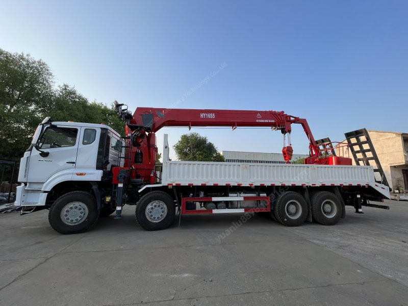
The HY16S5 truck crane from Haoyi is highly favored in Asian infrastructure projects and serves as a prime example of modern stability engineering. With a span of up to 7 meters, its dual hydraulic outriggers boast a 20% larger polygonal area compared to the base of older five-section outrigger models. Field test records from the Nanjing Metro line project demonstrate that, even under continuous slewing at 210°, the chassis roll remains below 0.3° at 90% of rated capacity. Operators commend the remote-controlled automatic outrigger leveling system and the Q690 high-strength boom sections for their predictable behavior. These design choices align with the principles outlined in this guideline: maximizing base width, monitoring inclination, and adhering to angle-dependent load charts.
8. Training, certification and continuous improvement
The U.S. Occupational Safety and Health Administration (OSHA) requires mobile crane operators to hold a recognized certification (§1926.1427). In addition to obtaining a license, repeatedly practicing scenario-based drills can strengthen muscle memory for settings. Recommended practice:
- Update the ability to interpret load charts once year.
- Hold a leg inspection seminar quarterly, using destructive pad testing.
- Conduct a toolbox talk on task issuance, collect near-miss accident data, and update the checklist template.
Many companies have also integrated telematics systems: tilt sensors and pressure sensors transmit real-time data to cloud dashboards, enabling security managers to review the quality of settings across multiple sites.
Conclusion
The impressive reach of a telescopic crane relies on its weakest setup step for safety. Fully extending the legs on a verifiable ground, precise control of the boom angle, and strict adherence to load chart limits constitute the three-point stability guarantee. Combining these practices with modern monitoring technology and comprehensive operator training, every lift, whether it’s a 300-kilogram HVAC unit or a 20-ton prefabricated beam, can be carried out confidently, efficiently, and in compliance with regulatory requirements.


