
Safe operation of a telescopic boom truck mounted crane depends on much more than its rated lifting capacity. Ground conditions, outrigger configuration, boom length, working radius, load weight, rigging and operator competence all affect the allowable lift. The load chart and operating manual for the exact crane model and configuration must always control the decision.
This guide explains a practical setup process for planners and operators. It is general information, not a substitute for the manufacturer’s manual, an approved lift plan or the laws that apply at the job site.
Safety rule: Never estimate capacity from the crane’s maximum tonnage alone. Confirm the total suspended load, actual working radius, boom configuration, outrigger position and the applicable load-chart entry before lifting.
Why Setup Changes Lifting Capacity
A crane creates a load moment: the suspended weight acts at a horizontal distance from the center of rotation. As working radius increases, the overturning effect increases. Extending the boom, lowering the boom angle or swinging into a less stable operating sector can therefore reduce available capacity even when the load itself does not change.
Outriggers enlarge the crane’s support area and transfer forces into the ground. They do not make weak ground safe, and partial extension must never be treated as equivalent to full extension unless the manufacturer supplies a specific load chart for that configuration.
Pre-Lift Setup Checklist
- Identify the crane model, boom and attachment configuration.
- Determine the total suspended load, including hook block, slings, shackles and attachments.
- Measure the maximum working radius required during the complete lift path.
- Check the ground for voids, backfilled trenches, underground services, slopes and soft areas.
- Select outrigger pads or mats using the expected reaction force and allowable ground pressure.
- Deploy outriggers in the configuration required by the applicable load chart.
- Level the carrier within the tolerance stated in the operating manual.
- Check overhead hazards, power lines, exclusion zones and the planned load path.
- Confirm that safety devices and the load moment system are configured correctly.
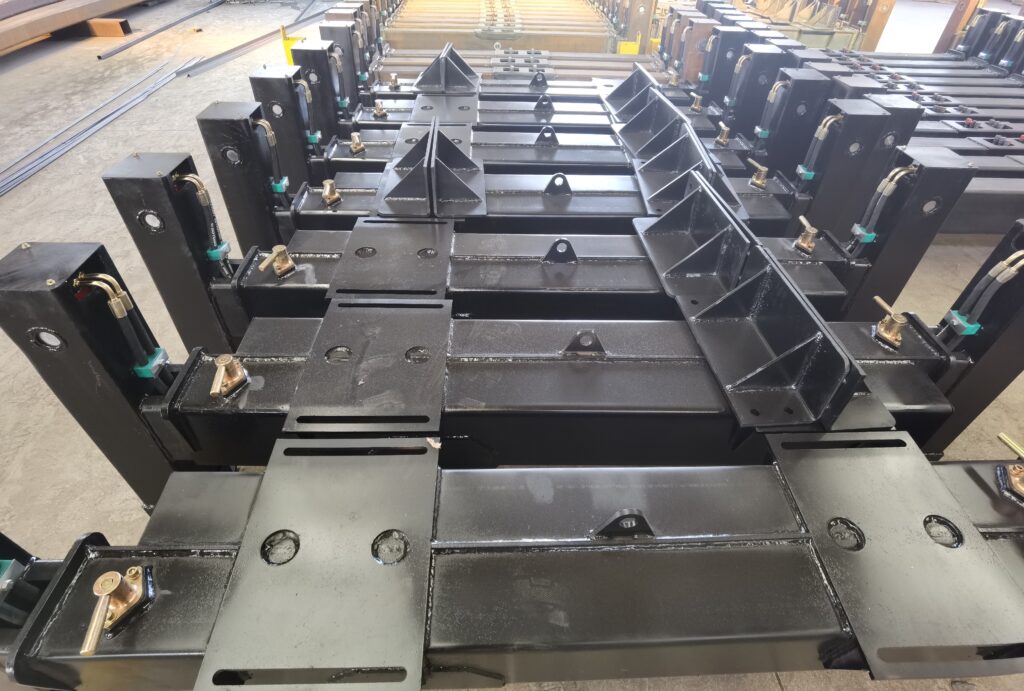
Outrigger Deployment and Ground Support
Follow the manufacturer-defined sequence for parking, braking, wheel restraint, beam extension, jack deployment and leveling. Keep each outrigger visible to the operator or a designated signal person while it is being extended and set. Blocking belongs beneath the jack float or the designated bearing surface, not beneath an unsupported section of the outrigger beam.
For work covered by United States construction rules, consult the applicable requirements in OSHA 29 CFR 1926.1404 as well as the equipment manual. Other countries and industries may apply different standards. The safest instruction is always the most restrictive applicable requirement.
Ground Evaluation
Visual inspection alone cannot confirm bearing capacity. Recently filled soil, pavement over trenches, underground chambers, retaining-wall edges and waterlogged ground can fail without much warning. A competent person should evaluate support conditions and determine whether engineered mats, larger pads or a different crane position are required.
Monitor the pads after the crane is loaded. Stop if a pad sinks, the carrier moves out of level, an outrigger loses firm contact or the ground begins to crack.
How Boom Angle, Length and Radius Affect Capacity
The load chart connects several variables: boom length, working radius, operating sector, outrigger configuration and allowable load. A lower boom angle usually produces a longer radius, but the operator should use the charted radius rather than relying on angle alone.
Load-Chart Procedure
- Determine the verified weight of the load and all lifting accessories.
- Determine the largest radius that will occur anywhere in the lift.
- Select the correct chart for the boom, jib, counterweight, outrigger and operating-sector configuration.
- Find the rated capacity at the required radius and boom length.
- Apply every reduction or restriction stated by the manufacturer.
- Do not interpolate upward, exceed the chart or assume the load moment indicator will correct an unsuitable plan.
For a fuller explanation, see how to read a crane load chart. OSHA also states that equipment must not be operated above rated capacity and that load weight must be established by a reliable method; see 29 CFR 1926.1417.
Common Setup Errors
| Error | Why It Matters | Better Practice |
|---|---|---|
| Using a fully extended chart with partially extended outriggers | The support geometry does not match the chart | Use only a chart approved for the actual configuration |
| Estimating load weight | Rigging and attachments can push the lift over capacity | Verify the complete suspended load |
| Judging radius from boom length | Radius is horizontal distance, not boom length | Measure or calculate the actual operating radius |
| Small pads on weak ground | High ground pressure can cause settlement | Size support materials for reaction force and soil capacity |
| Using a generic wind limit | Permitted wind depends on the crane, boom and load area | Follow the manufacturer’s limits and lift plan |
| Continuing after the carrier moves out of level | The load chart may no longer apply | Stop, lower the load safely and correct the setup |
Operator Competence and Communication
Operators need more than a certificate. They must understand the controls, safety devices, load charts and configuration of the specific equipment assigned to them. Employers should also evaluate the operator’s ability to recognize hazards and perform the planned work. For U.S. construction operations, the detailed requirements are available in OSHA 29 CFR 1926.1427.
Use a qualified signal person when the operator cannot clearly see the load path or outrigger deployment. Agree on communication methods before the lift and stop work if communication is lost.
Frequently Asked Questions
Must outriggers always be fully extended?
Use the configuration required by the manufacturer and the selected load chart. Partial extension is acceptable only when the equipment has an approved chart and instructions for that exact setup.
Can the load moment indicator replace the load chart?
No. It is an operational aid, not a substitute for knowing the load, planning the radius and selecting the correct chart before lifting.
How much capacity should be added as a safety margin?
Do not create a universal percentage or exceed rated capacity. The lift plan must remain within the manufacturer’s chart and apply any required deductions for rigging, attachments, wind, operating sector and other conditions.
Conclusion
Stable telescopic crane operation begins with verified ground support, the correct outrigger configuration and disciplined use of the load chart. If the setup, load or environment changes, stop and reassess before continuing.
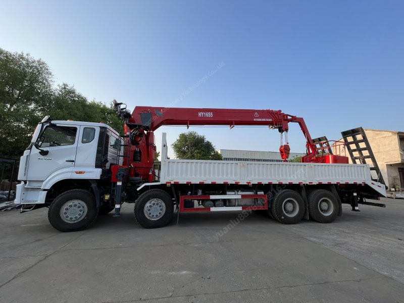
HAOY provides telescopic boom truck mounted cranes and configuration support for different chassis and lifting applications. Contact our technical team with the load weight, working radius, chassis information and operating environment for model-selection assistance.